
Categories
Important Links

Seagate HDD PCBs malfunctions and check methods
Most Seagate HDD PCB's malfunctions are caused by the below components:
- Motor Combo IC
- Power control Model
- SV power supply's diode, FET, etc.
Check the Seagate HDD PCB's malfunctions as the below methods:
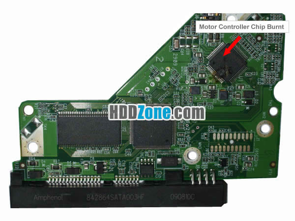
1. Check the Motor Combo IC
Motor Combo IC damage will cause the HDD's spindle motor and voice coil motor don't work.
Test method:
check the Motor Combo IC's power feet, electrical motor's power feet and heads-stack's power feet. In normal, No. 52 foot is the power foot of Motor Combo IC. The supply power should be 3. 25V. If it is not, it means the supply circuit is fault. No.65 - No. 67 are the feet of electrical motor. The supply power is 7-8V. If it is not, it means the Motor Combo IC damaged, No.3 and No. 5 are the feet of head1 and head 2. The supply power is 5-6V. Head's No. 11 foot is controlled by gate circuit. This voltage is leaping voltage.
2. Check the Power Control Model
Check method:
test the Model's input and output voltage. The voltage is 3.25V. The voltage is the power supply of Motor Controller IC. If the input voltage is normal, the output voltage is abnormal, it means the Power Controller Model was damaged.
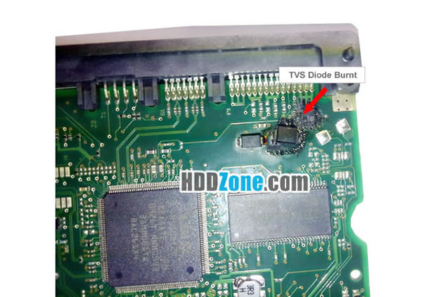
3. Check the 5V, 12V power supply's diode, FET, etc.
If the 5V supply line's component was damaged, it will not supply the PCB with 5V power supply. The PCB will not work as normal.
Check the FET's methods:
First, set the DMM on the “Rxl00. The 2 pens connect to Drian D and Source S. Then hold a screwdriver's insulated handles and using the screwdriver's metal bar touch the Grid G(inject the induced voltage). The digitals in the DMM will be large or small. If the digital change large, it means the FET amplification is strong. If the digital is not change, it mean's the FET has been damaged.
The methods of judge the supply's diode:
First, set the DMM on the “Rxlk” or diode block. Then connect the 2 pens to diode's 2 sides. If the positive and negative resistance values are infinite, the diode internal circuit damage; If the positive and negative resistance values are 0, it means the diode is short-circuit. If there is no difference between the positive and negative resistance, it means the diode's quality is not good. The diode should not be used any more.Why Choose US?
✓ Over 1000+ PCB Types;
✓ 100% Tested Working;
✓ Free Shipping Worldwide;
✓ Secure Shopping by Paypal;
✓ Professional Technical Support;
✓ Customer Loyalty Discount;